


Our EMR technology which our company originally patented has proven to be a basis for development of graphics applications, since the beginning of computer graphics.
It has already become the de facto standard pen input for professional creators.
・Precise pen coordinate detection
・Precise pen pressure detection
・Precise pen hovering height detection
・Battery free, slim pen available
・Flexibility in pen nib selection
(no need to be electrically conductive)
Digitizing Board Structure
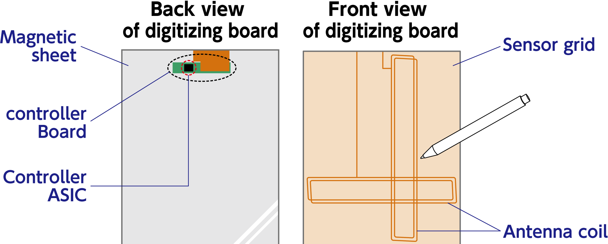
The structure of Wacom EMR digitizing boards is quite simple. The main parts are a sensor grid board, a magnetic sheet and a controller ASIC.
The sensor grid board has many rectangular coils which work like a transformer primary coil, to transmit and receive magnetic energy to and from the secondary coil in the pen. The magnetic sheet acts as the conductor of magnetic flux between the sensor grid board and the pen.
Wacom has been developing EMR controller ASICs for over thirty years. The capability to design analog and digital mixed-signal ASICs is one of our strengths.
Pen Structure and Pressure Detection
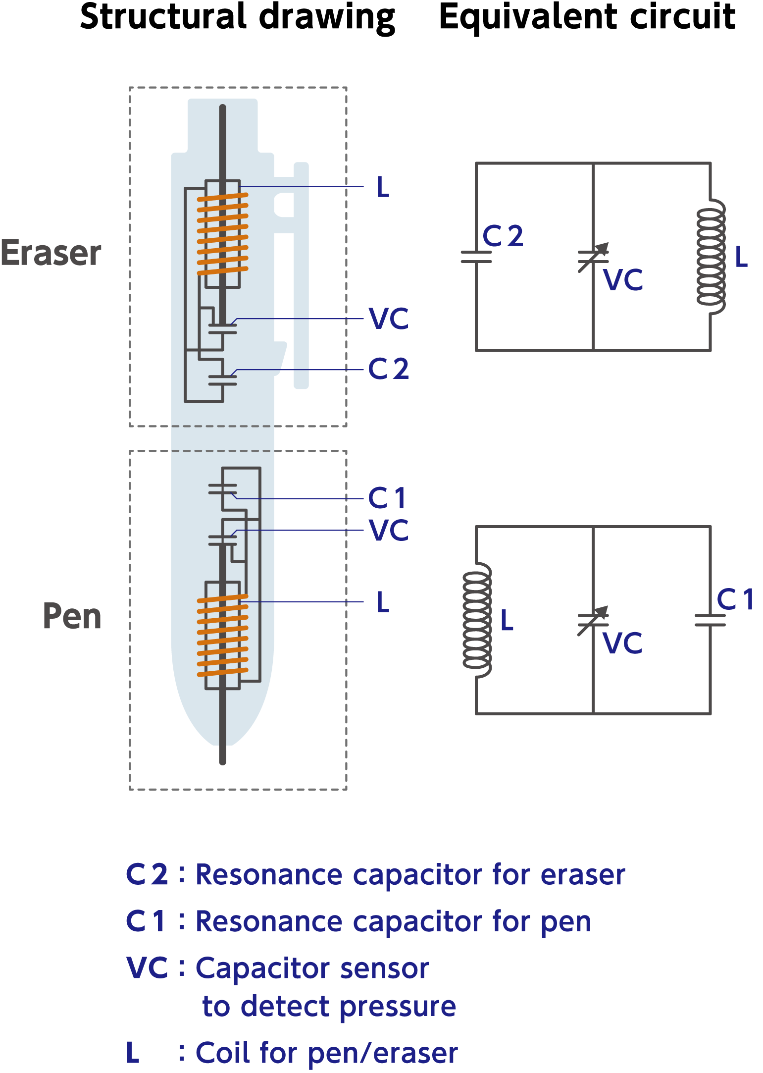
Below is the structure and the equivalent circuit diagram of the electronic pen. The resonance circuits for the pen portion and the eraser portion are independent of each other.
The controller ASIC recognizes the difference between the pen and the eraser based upon the resonance frequency. It also recognizes the pen pressure exerted on the surface of the tablet by detecting the frequency drift, which is caused by the value change of the VC capacitor sensor.
EMR Digitizer Controller ASIC Block Diagram
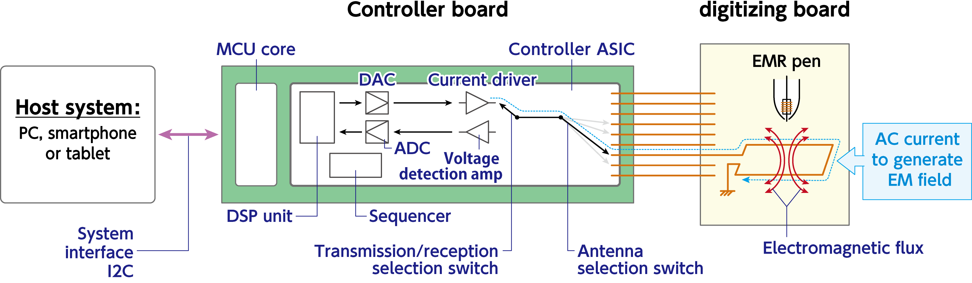
This is the block diagram for the EMR digitizing board controller ASIC. The controller ASIC is comprised of a microcontroller unit (MCU) core, a digital signal processing unit, an analog-to-digital converter (ADC), a digital-to-analog converter (DAC), a current driver and numerous analog switches.
The DAC outputs the wave form to drive one of the digitizing board coils. Then the ADC digitizes the wave form from the same digitizing board coil.
Transmission and Reception Operations Utilizing Electromagnetic Resonance (EMR)
This page explains the “electromagnetic energy reception by the pen while in the excited magnetic field mode”, through our company’s EMR principle.
The controller ASIC selects one of the grid board coils, and drives an AC current of the same frequency as the pen’s resonance frequency to the coil.
The grid board coil and the coil in the pen function like a primary coil and secondary coil consecutively, so the voltage generated at both ends of the coil of the electronic pen causes the resonance circuit of the pen to resonate and store electrical energy.

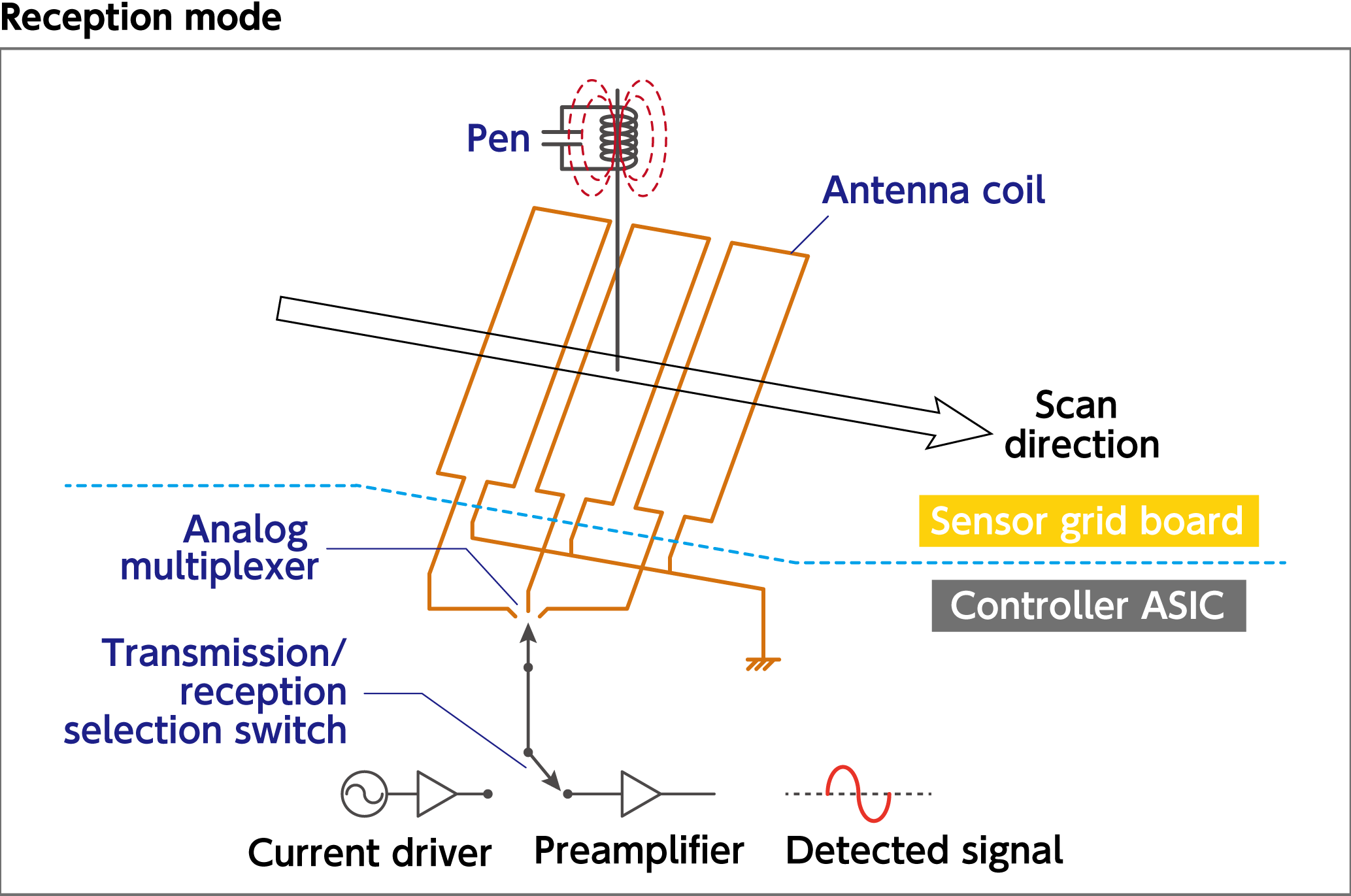
Once the pen starts resonating, thereby storing electrical energy. the controller ASIC switches to the “reception mode” to receive energy from the pen.
The amplitude of the detected signal (see the lower right chart) represents the distance between the grid board coil and the pen coil.
The resonant energy from the pen is returned to the grid board coil, with the coil in the pen functioning like the primary coil, and the grid board coil acting as the secondary coil.
By detecting this voltage, the presence of the pen above the grid board coil is detected.
The analog multiplexer switches the grid board coil to scan the whole screen area sequentially, and creates a map of the detected signal strengths.
Producing Pen Coordinates
This animation demonstrates how the exact position of the EMR pen is calculated.
As explained in the previous page, the controller ASIC scans all the coils to derive each signal’s strength.
The calculation algorithm interprets this signal strength dispersion as a quadratic curve, and differentiates it to determine the exact position of the pen.
Basic Algorithm to Calculate the Coordinate Values:
- Measure the pen signal strength of each antenna by switching between the antennas, in the order of the antenna arrangement;
- Approximate with the above-mentioned quadratic curve;
- Derive the quadratic curve’s peak position by the differentiation, to determine the pen’s coordinates.